

Linear Actuators
×4Section 1: Actuator Mounting
8" or 12" stroke length, with wall bracket pre-installed
8" or 12" stroke length, with wall bracket pre-installed

Powder coated black aluminum for mounting an actuator to a wall

Powder coated black aluminum for connecting tube members to an actuator

8" actuator with floor mount and glide bracket installed

Actuator floor mount (pre-installed on actuator)

Glide bracket for guiding the drop mount bracket during operation (pre-installed on actuator)

Powder coated black aluminum bracket for lowering the frame attachment point to below the top of the actuator

Powder coated black aluminum mount to connect the Drop Bracket to the actuators

Powder coated black aluminum for connecting tube members to a location on the Drop Bracket

Cross beam tube assemblies consist of one cross beam inner tube and one cross beam outer tube and run perpendicular to the frame and act as cross bracing members.

Side rail beam tube assemblies consist of one side rail inner tube and one side rail outer tube and are the rails that run lengthwise along the frame.

Rubber noise dampeners that eliminate rattling between the tube members

Secure and quick to install pins that connect the tube members to the joints in the frame - also have a rubber sheath for rattle reduction

Low friction tape that allows the tube members to slide freely without scratching or rattling

Low friction tape that allows the tube members to slide freely without scratching or rattling

Rubber strap spacers to stabilize platform, dampen noise, and protect frame.

Rubber strap spacers to stabilize platform, dampen noise, and protect frame. Installed on power board cover.

Powder coated black aluminum bracket for securing platform to frame

The power board is the brain of the system that controls all of the functionality of the Tilt Bed.

Powder coated aluminum cover to protect wiring and power board.

Full functionality controller.

Frame mounted magnetic mount for the main controller.

Wall mounted magnetic mount for the main controller.

14 AWG wire that supplies 12VDC to the power board from the large coiled cable on the corner of the frame supplying power.

14 AWG wire that supplies 12VDC from your DC fuse panel to the large coiled cable on the corner of the frame supplying power.

4-wire coiled cable that both supplies 12VDC to the power board and connects the associated actuator to the Y-cable.

18 AWG cable the connects the power board to two actuators.

2-wire coiled cable that connects the associated actuator to the Y-cable.

Ethernet cable that allows the controller(s) to communicate with the power board.

Zip ties for securing coiled cables at each actuator to prevent strain on quick disconnects.

Cuttable wiring conduit.

Spade connectors for connecting power supply to power board

Velcro cable ties for securing wiring conduit if cable bulk prevents it from staying closed

1/4"-20 x 5/8" stainless steel screws with a black oxide coating for attaching drop mount parts together

Stainless steel #8-32 x 2" socket flat head screw, nylon insert lock nut, and washer. For securely mounting floor mounts to cabinet.

1/4-20 x 1/4" stainless steel set screws used for securing bi-directional joints and electronics frame mounts in place (quantity depends on number of electronics frame mounts ordered)

1/4"-20 x 3/4" stainless steel screws with a black oxide coating for attaching U-bracket to sleeping platform

For securing wall brackets to furring strips.

For securing actuator shaft brackets to wall mounts.
Set screws for securing bi-directional joints and tube mounted electronics in place.

This section will cover installing the wall mounts.
The wall mounts will locate the corners of the frame as shown in the overview image below.
Position wall mounts with threaded holes facing away from the center of the bed.
If uncertain, err on the side of placing wall mounts slightly closer together; the platform can overhang later.
The wall mounts should be installed as square as possible relative to each other, but small misalignments (within 1/8") are not an issue.
Secure all four wall mounts with wood screws into a solid furring strip (or equivalent solid structure).
The wall brackets must be mounted into a solid structure and secured tightly. If the
brackets are not rigid, the actuators may flex or feel loose.
Secure all four actuators to the wall brackets using 1/4-20 x 1" button head cap screws.
Place a bi-directional joint on top of each actuator with the pivot joint fins facing the other actuators. Secure with a 1/4-20 x 1-4" set screw.
The set screw should be installed in line with the motor as shown in the image below (otherwise the set screw will fall into the hole in the actuating shaft).

This section will cover locating and installing the drop mount ready actuators using floor mounts.

Each drop mount requires three parts to be assembled onto the drop mount ready actuator:
Before installing anything, it is a good idea to determine the proper location and orientation of all 4 actuators
Below are a few important things to keep in mind for a successful installation:

Ensure there is at least 1/2" of space (measured from the edges of the floor mount) all the way around the actuator.

Van walls are curved - more so near the ceiling - and it is important to ensure the actuator mount will not collide with the wall when fully extended.
There are a couple ways to verify this:
Option 1: Measure 21.5" from the point where the top of the floor mount meets the actuator base, OR
Option 2: Place the actuator mount on the actuator and measure 8" up from the corner closest to the wall
The floor mounts should be installed as square as possible relative to each other, but small misalignments are not an issue due to the flexibility of the frame design.

Before securing actuators or installing any drop mount assemblies, confirm all three orientation checks below.
Incorrect orientation will prevent proper operation later.
⚠️ Important:
Two actuators will have the glide bracket installed in one direction, and the other two will be flipped.
If you cannot make all three orientation checks pass on an actuator, swap it with another actuator until they do.

After determining the locations of the actuators, it is time to secure them in place.
Option 1 (recommended): If you have access to the underside of the mounting surface, it is best to use the included through bolts mounting hardware.

Option 2: If you can't install the through bolts, you can use #8 wood screws that are fully secured through a minimum of 3/4" plywood.
The floor mounts must be mounted onto a solid structure and secured tightly. If the mounts are not rigidly installed, the actuators may flex or feel loose.

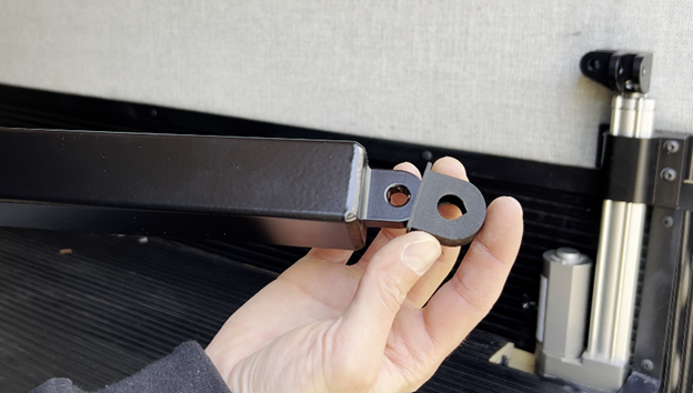
Attach the actuator mounts to the drop brackets using 4x 1/4-20 x 5/8" drop mount screws
Ensure the side of the actuator mount with the third threaded hole faces towards the bed when installing

Place the drop mount on the actuator and determine where on the bracket you want to install the bi-directional joint.
This will be the height where the frame attaches to the drop mount.
NOTE: The 3rd and 4th holes from the bottom of the drop bracket are reserved for the glide bracket and cannot be used
The 3rd and 4th holes from the bottom of the drop bracket are reserved for the glide bracket and cannot be used

Secure the bi-directional joint in the location determined in the previous step - making sure the fins face towards the adjacent bed corners (towards the other mounted actuators)
Ensure the bi-directional joint is installed so the fins face towards the adjacent bed corners - otherwise the frame will not attach properly

Place the completed drop mount assembly onto the actuator
Using two 1/4-20 x 5/8" drop mount screws, secure the glide bracket to the drop bracket until snug via the threaded inserts
Tighten until snug - do NOT overtighten
Only secure glide bracket screws until snug, do NOT overtighten
Installing linear rails on just two adjacent actuators is sufficient to eliminate sway. Using only two reduces both cost and installation time.
It is highly recommended to install the linear rails on the actuators located either at the rear doors or at the front of the van, whichever is easiest to access.
Most of the lateral force applied to the frame runs lengthwise with the van. For best stability, securing the rear two actuators or the front two actuators with linear rails is optimal.
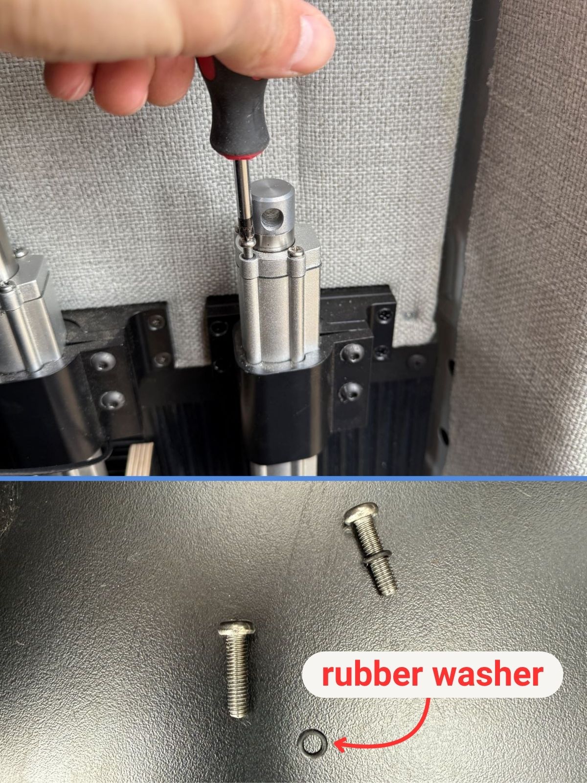
Remove the four machine screws from the top of the actuators.
Ensure you retain the rubber washers that are on each screw.
Watch out! Sometimes the rubber washers on the screws don't come out with the screws. Make sure to find each one and keep them for the next step.
Place the rubber washers in the indents on the actuators where the machine screws were removed.
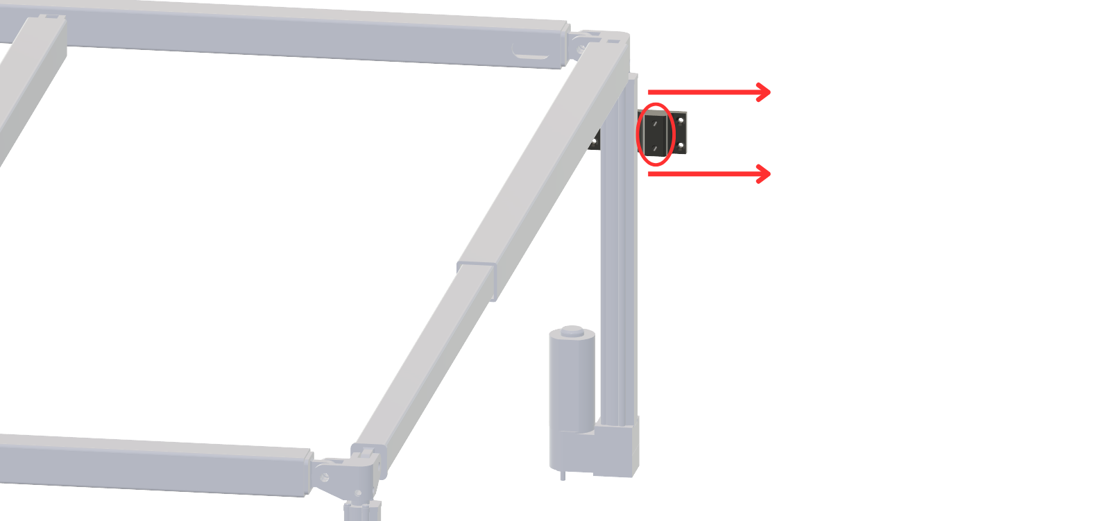
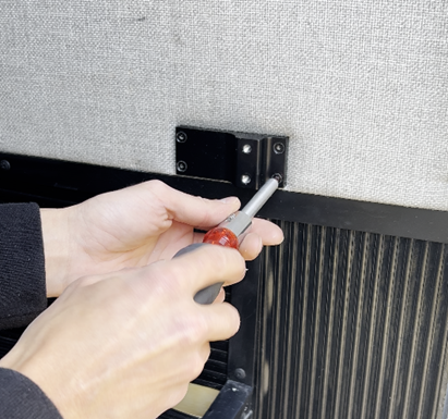
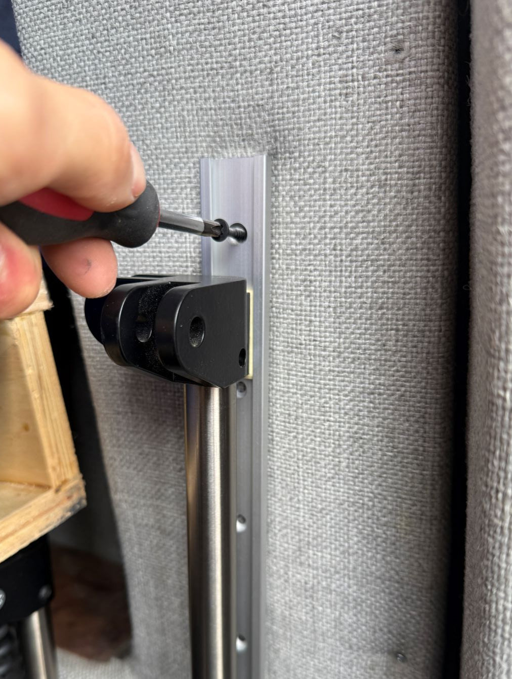
Install the linear rail mounts and secure with M4x30 flat head machine screws.
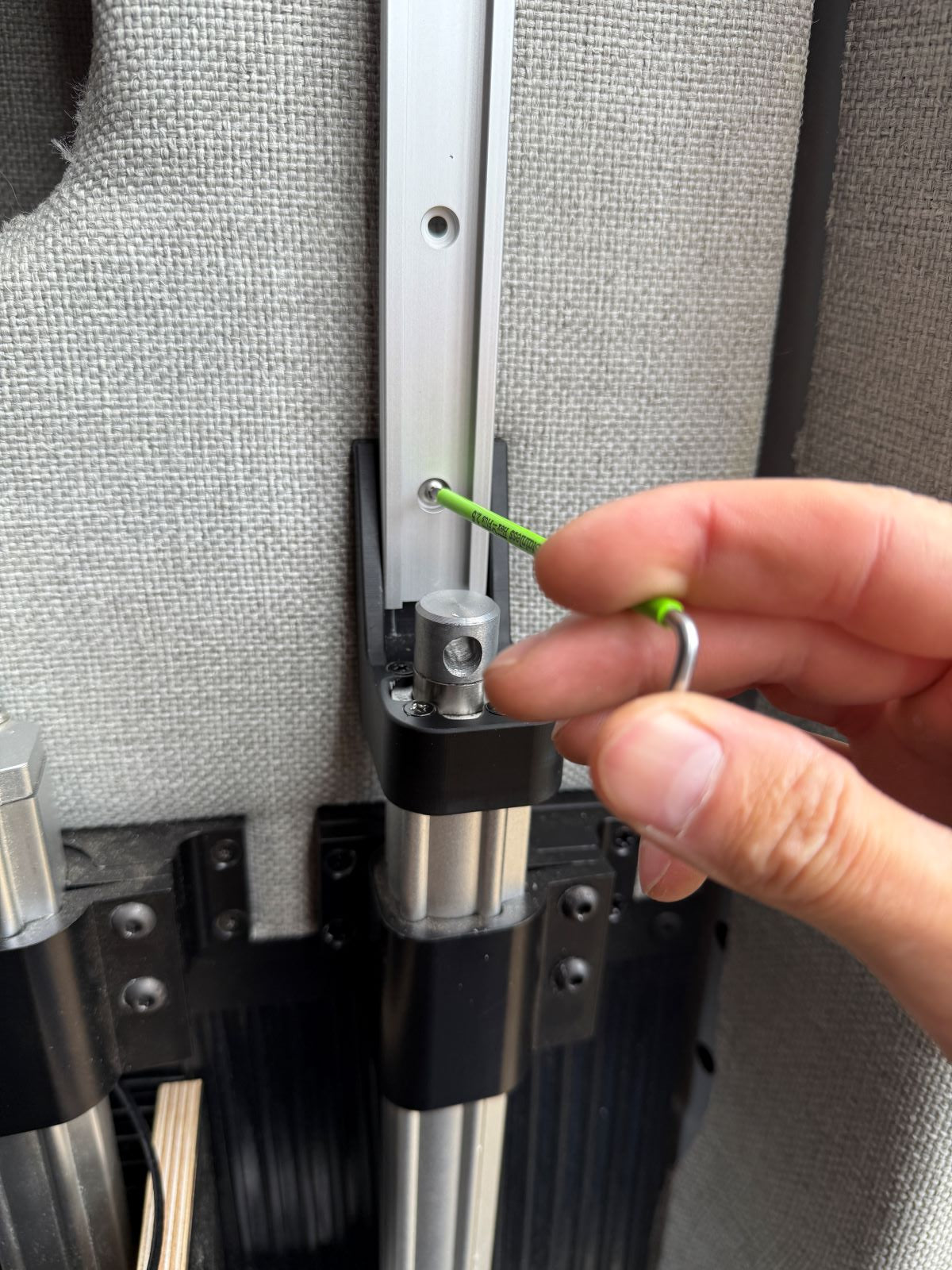
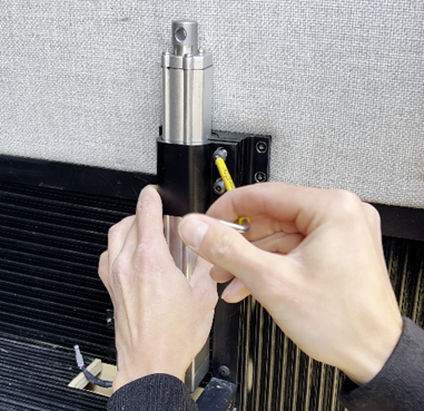
Install the linear guide rail in the linear rail mount using M4x8 button head machine screws with a 2.5mm hex key.
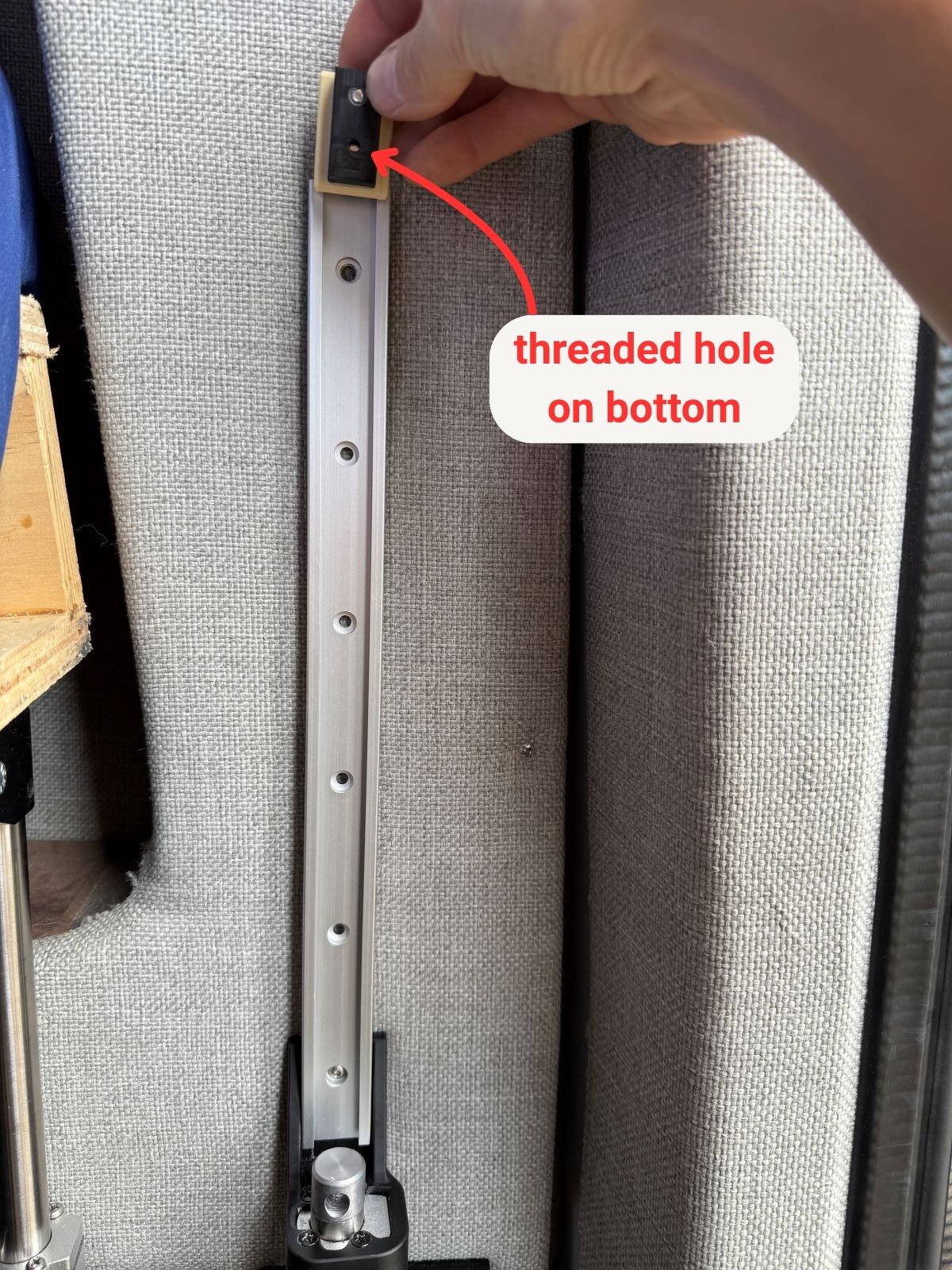
Slide the linear rail carriage in the guide rail from the top with the threaded hole at the bottom as shown in the image.
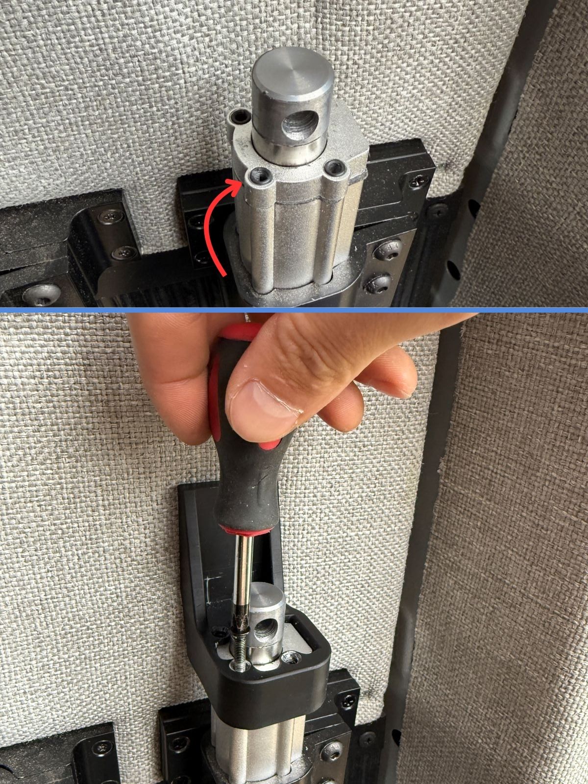
Place a bi-directional joint on top of each actuator with the pivot joint fins facing the other actuators. Secure with a 1/4-20 x 1/4" set screw.
The set screw should be installed in line with the motor as shown in the image below (otherwise the set screw will fall into the hole in the actuating shaft).
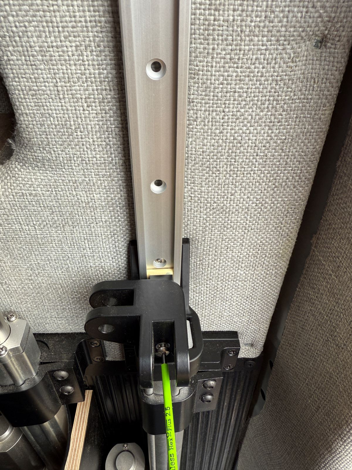
Align the hole in the bi-directional joint with the threaded hole in the linear rail carriage. Secure with a M4 x 30mm button head cap screw using a 2.5mm hex key.
Don't forget to re-tighten the set screw on the bi-directional joint.
Securing the top of the rail will be completed later when the bed is powered on.
⚠️ Leave the top of the rail unsecured for now.
This step will be repeated when the bed is operational to remind you to complete it.

This section will cover installing the frame assemblies.
Place noise dampeners on the ends of each of the tube members.
Insert the cross beam inner tubes into the cross beam outer tubes and the side rail inner tubes into the side rail outer tubes.
Ensure the pivot joints on the ends of each tube assembly are oriented in the same plane (not rotated by 90 degrees).

Attach the two side rail tube assemblies along the sides of the frame to the bi-directional joints using SLIC pins in the orientation shown.
Note: the orientation of the long-beam tube assemblies is based on which side of the bed is the head (where your pillows go!)
⚠️ Important: The side rail inner tube must point towards the head of the bed.
If the side rail inner tubes do not point towards the head of the bed, the wiring will not run smoothly.

Next, attach the four cross beam tube assemblies across the frame using SLIC pins
Note: the orientation of the cross beam tube assemblies is based on where the 12VDC source will come from.
The cross beam OUTER tubes must point towards the side of the bed where the 12VDC source will come from
⚠️ The image below is just an example. If your 12V source is on the opposite side rail, your cross beam OUTER tubes will point towards the opposite side as well
If the cross beam outer tubes do not point towards the 12VDC source side, the power supply cable can be strained as the bed moves
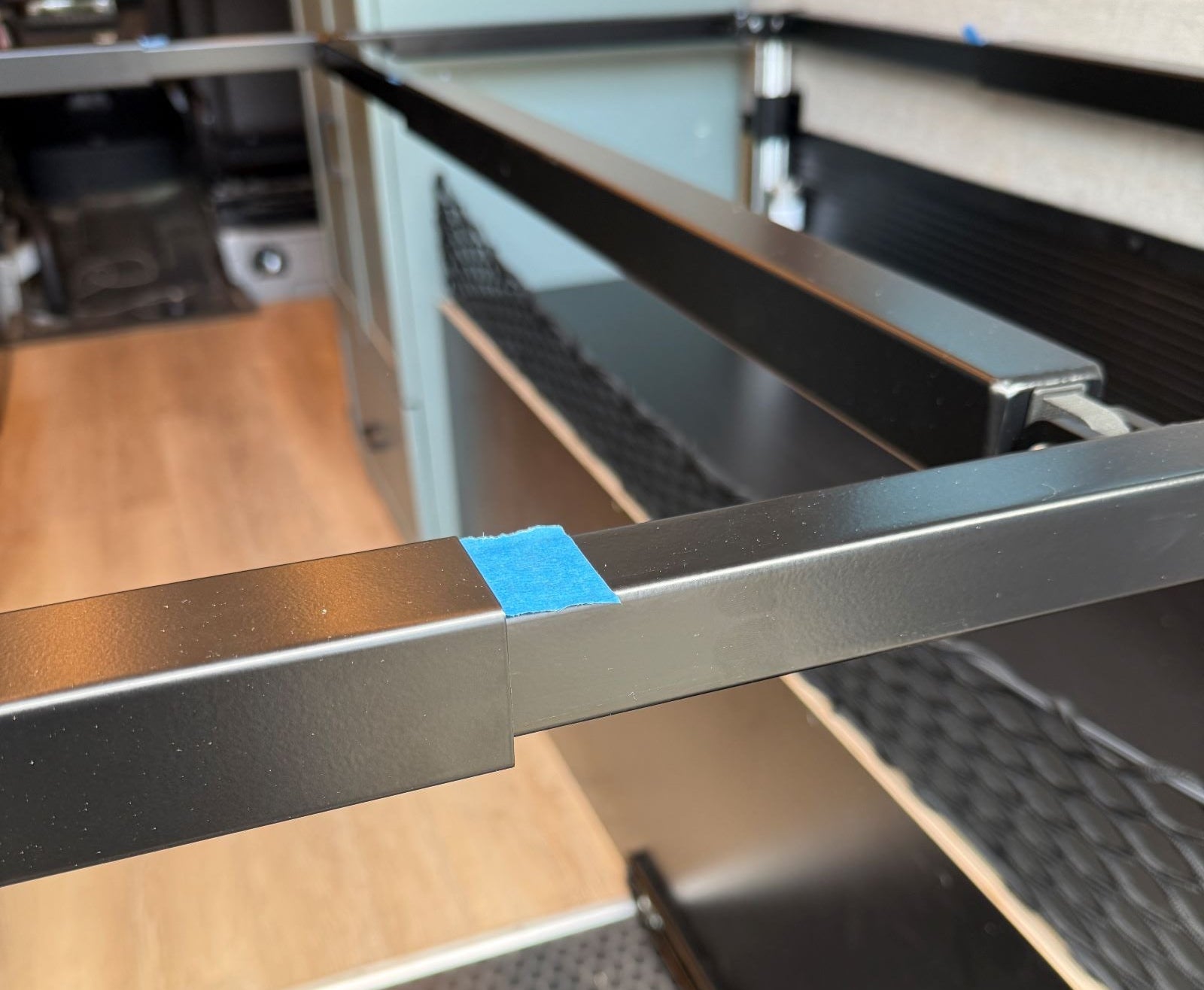
Use a tape that leaves no residue (like blue painter's tape) to mark the locations where the inner tubes meet the outer tubes for all six tube assemblies
Make sure to mark the location on the smaller INNER tubes, not the outer tube
If your kit includes a frame mount for the main controller or an auxiliary controller, decide where you want to install it on the frame and mark that location as well before proceeding
Remove the tube assemblies and keep track of their installed locations/orientations.
If you are having trouble removing SLIC pins, give them a twist!

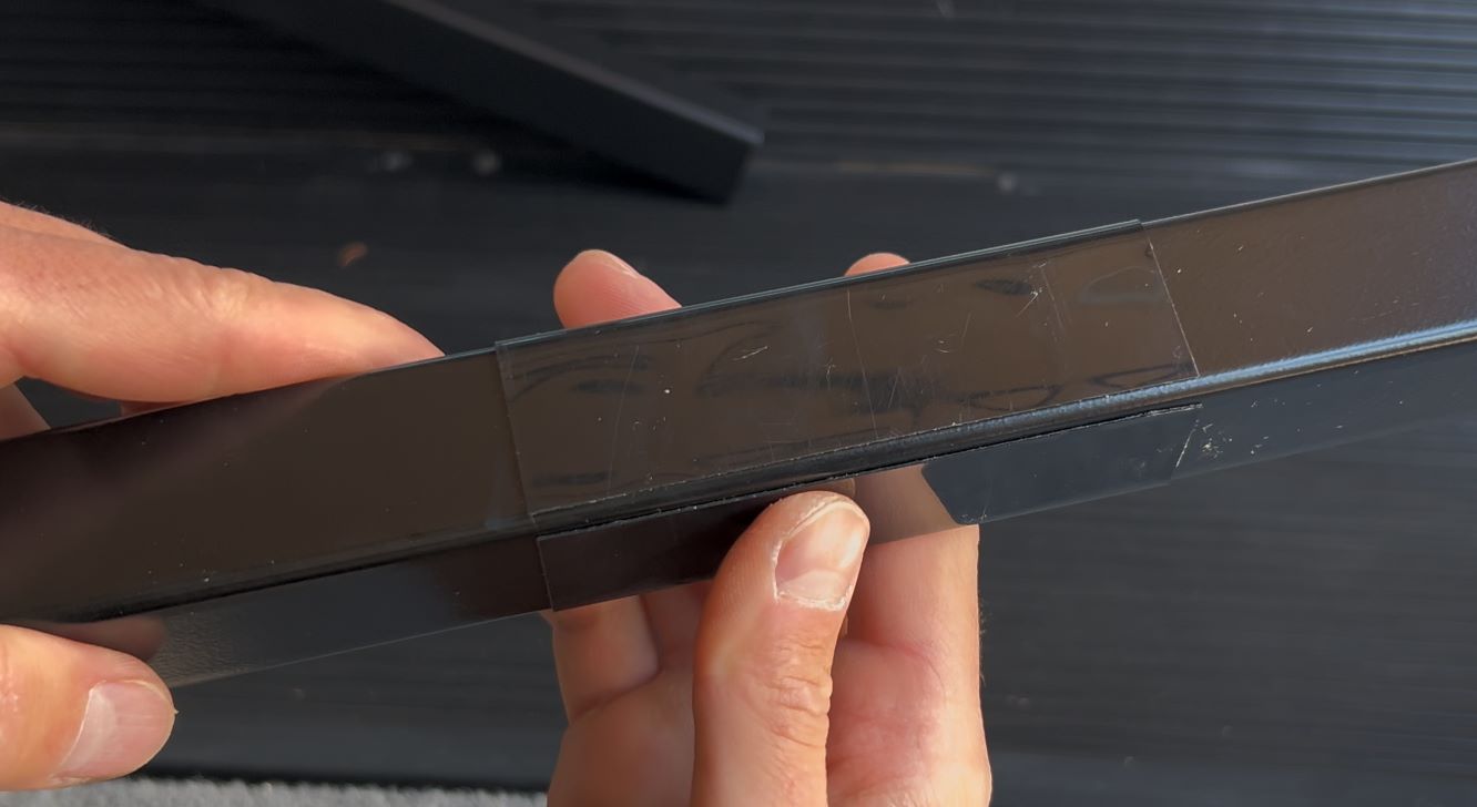
The locations you marked earlier are where the large glide tape pieces will go.
Apply the glide tape on the inner tube about 1.5" away from the mark, on the opposite side of the pivot joint.
This placement ensures the glide tape is fully covered by the outer tube once the frame is reassembled.
⚠️ IMPORTANT: The glide tape must be installed on the correct side of the mark. If placed on the wrong side, the outer tube will not slide over the tape when reassembled.
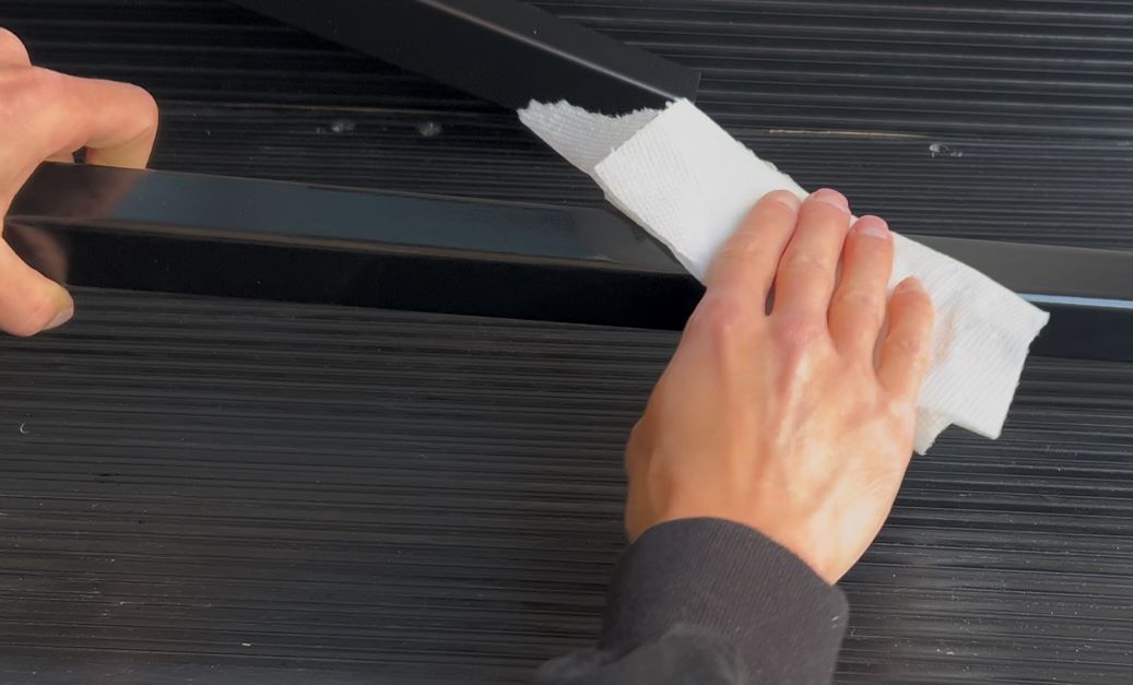
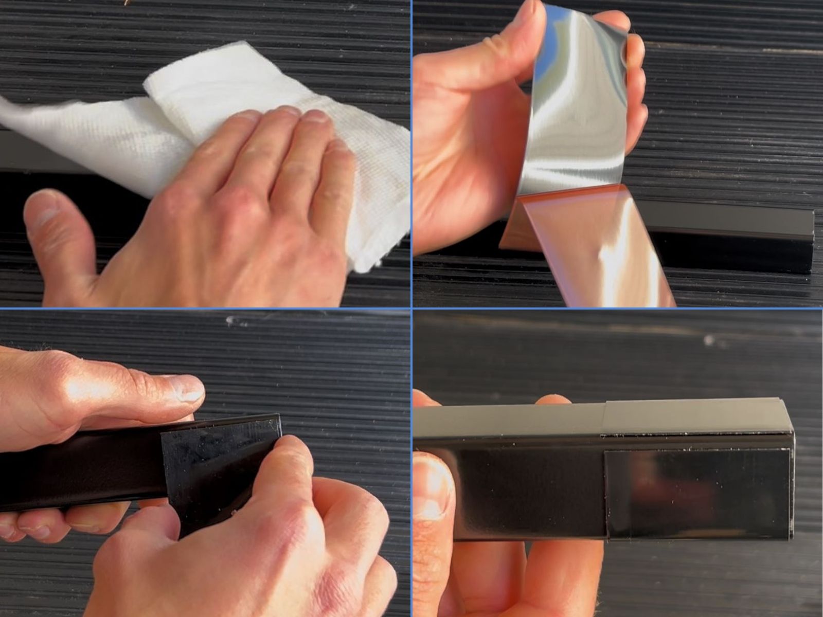
Wipe the area on the inner tube with isopropyl alcohol to remove dirt and grease for best adhesion.

Peel the backing from a piece of large glide tape.
Align the 4" edge of the tape immediately after the rounded corner.
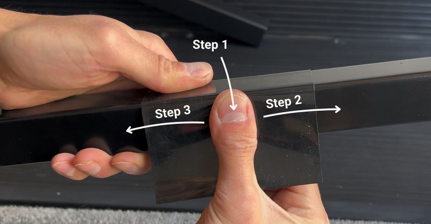
Pull the tape taut and press firmly down the middle. Smooth outward from the center to each edge to push out air bubbles.
Repeat until all sides are secured.
The final corner should look like the image below. Press firmly all over the tape to ensure proper adhesion.
Repeat the same process on the very end of each inner tube with the small glide tape
NOTE: Depending on the dimensions of your bed, the large and small glide tape may be installed right next to each other.
Verify each inner tube now has two pieces of glide tape, one large piece where the inner and outer tubes intersect and one small piece at the end.
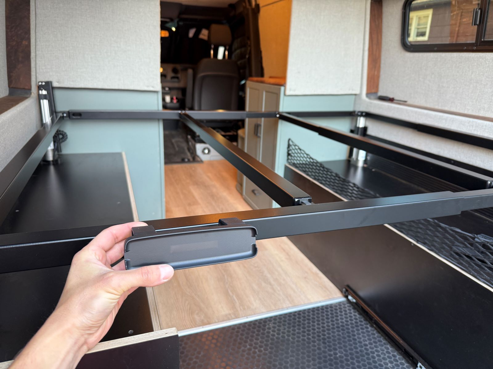
If your kit includes a main controller frame mount or an auxiliary controller, slide the mount(s) onto the marked location(s).
Mounts fit directly on the outer tubes.
Secure each mount with two 1/4-20 x 1/4" set screws until snug.
Tightening beyond snug may crack the mount case. Only tighten enough so the mount does not move.

Reinstall the tubes in the same orientation as before the glide tape was applied:
- Side rail inner tubes -- point toward the HEAD of the bed
- Cross beam outer tubes -- point toward side of bed with the 12V power source

Slide the power board onto the short outer tube closest to the HEAD of the bed, with the board facing the HEAD
⚠️IMPORTANT: The power board must be installed in the location and orientation in the image below to prevent wiring and control issues. The text on the front of the board must be oriented upright.
Position the power board so it is as close to the center of the bed as possible
Secure in place with two 1/4-20 x 1/4" set screws until snug
Tightening beyond snug may crack the mount case, only tighten enough so the mount does not move
Install the spacers in the marked locations.
(1) Inner tube spacers: Install one inner tube spacer near the pivot joint of each cross beam inner tube and two on each side rail inner tube as shown.
(2) Outer tube spacers: Install two inner tube spacers on all cross beam outer tubes and side rail outer tubes. Only install one on the cross beam outer tube with the power board.
(3) Power board spacers: Spacers on the power board will be installed with the power board cover at a later step.
With the frame fully assembled and any electronics in place, you are ready to begin wiring.
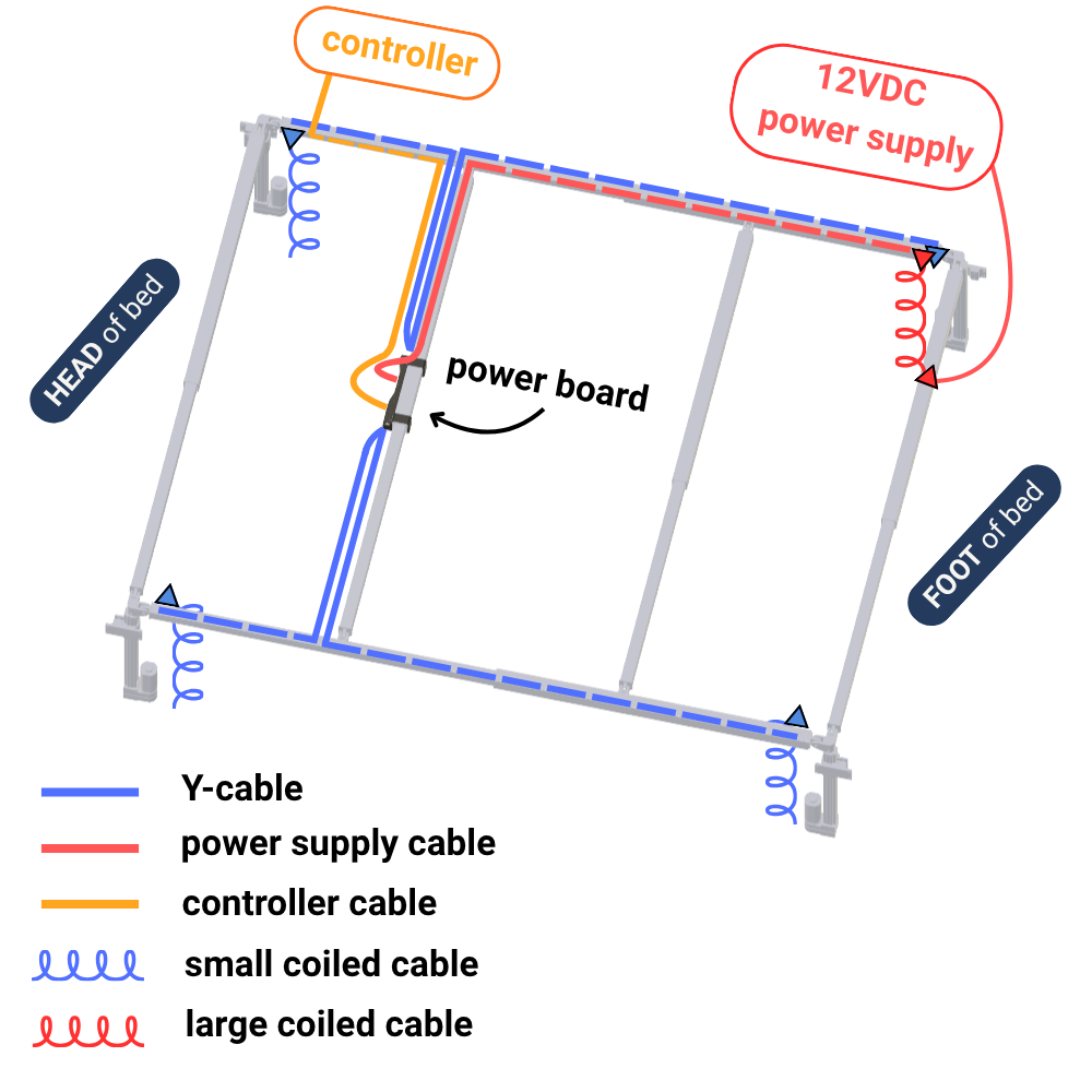
The wiring diagram shows one example. Your setup may differ depending on where your power supply and controller are located. Run cables to match your specific layout.
🔌When pulling cables through the frame, you will notice extra wire at each corner. This is expected and will be cleaned up in a later step.
1. Connect the large coiled cable (image) to the long power supply cable (image) at the actuator that will serve as your 12VDC input.
2. Run the long power supply cable through the frame to the power board spade connector inputs.
3. Cut to length, leaving about 3″ of slack.
4. Strip the ends, crimp on the blue spade connectors, and plug into the power board (red = +12V, black = GND).
5. Connect the short power supply cable (image) to the base of the large coiled cable and run to your 12VDC source - but leave de-energized.
1. Each Y-cable (image) has a short leg and a long leg. Run each leg to the appropriate actuator:
2. Repeat for both sides of the bed.
3. Connect the short legs and long legs to the actuators via the small coiled cables (image).
4. Plug the Y-cables into the power board 4-pin connectors.
1. Connect the controller cable (image) to the power board.
2. Run the controller cable to your controller location.
3. If your kit included an auxiliary controller, run the second controller cable to your auxiliary controller location.
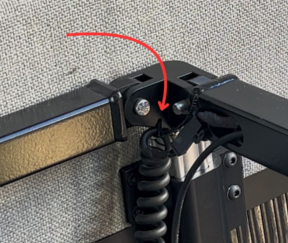
Upper strain relief: Use zip-ties through the holes in each bi-directional joint to secure the top of every coiled cable.
Make sure the upper zip ties are below the quick disconnect so the actuator can extend without stressing the connection.
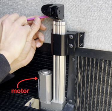
Lower strain relief: Use zip ties to secure the bottom of the coiled cables to the top of the motor housing. Similar to the upper strain relief, make sure the lower zip ties are above the quick disconnect.

Lower strain relief: Use zip-ties through the mounting hole on the actuator motor to secure the bottom of every coiled cable.
It is important to place the zip-tie on the coiled cable itself so the quick connect is not stressed during operation.

Upper strain relief: Use zip-ties through the mounting hole on bi-directional joint to secure the top of every coiled cable.
It is important to place the zip-tie on the coiled cable itself so the quick connect is not stressed during operation.
If your frame is installed below the top of the actuator motor (as shown in the images), the coiled cable should run over the frame to the wire entry hole, as shown.
Secure the large coiled cable in the same manner.
Before securing the wiring to the power board, one side of the bed needs to be raised to its maximum height to maximize the wiring distance from the power board to the actuators.
Double check all the connections are secure before applying 12VDC to the short power supply cable.
Before applying 12VDC power to your Tilt Bed:
⚡Connect 12VDC to the short power supply cable.
Press the reset button on the controller to establish a connection.
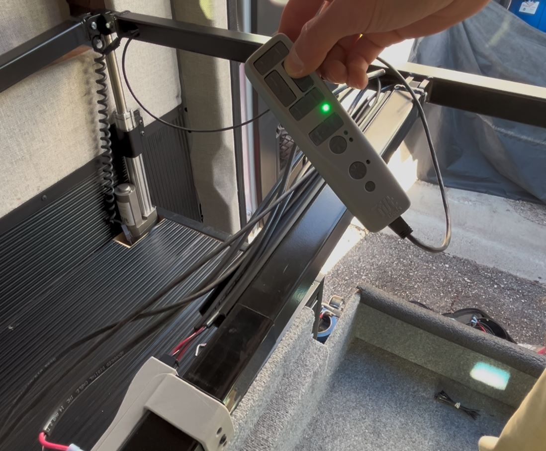
Ensure the area is clear and raise one side of the bed to it's maximum height.
The bed frame will widen as it lifts - this is what allows the Tilt Bed to work!
Hit the Reset button (closest to the Tilt logo) on the controller.
If it is still not working - unplug the power, wait a few seconds, and plug it back in.

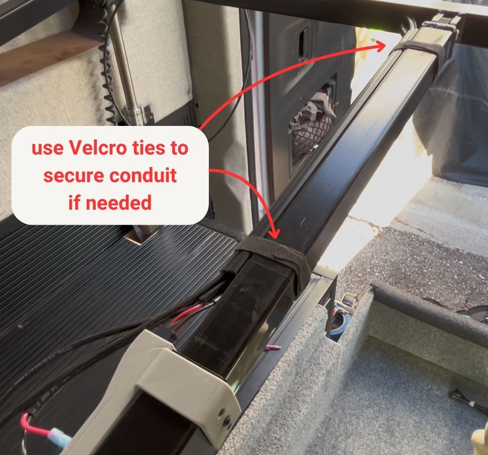
With the bed at its maximum width, the wire conduit can be installed on the inner tube only. Outer tube wire conduit will be installed at a later step.
1. Cut the wire conduit to size, allowing at least 4" from the edge of the outer tube.
2. Install in place using the adhesive backing.
3. Enclose cables in the conduit.
4. If the conduit won't stay closed due to cable bulk, secure with Velcro cable ties at each end.
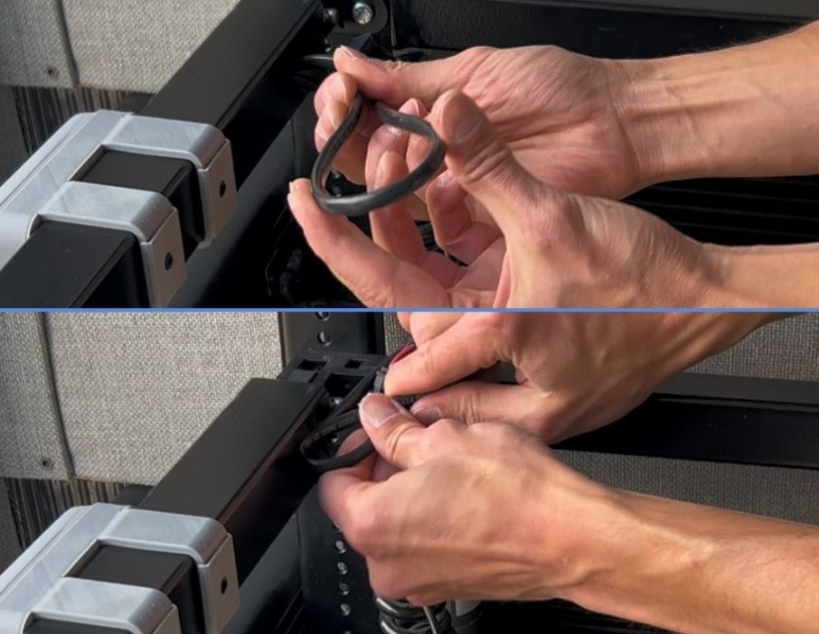
Gently bend extra cable (do not crease) and tuck it inside the frame.
Leave some excess controller cable for removing the controller from the mount.
Lower bed all the way back down to proceed with cutting the sleeping platform.
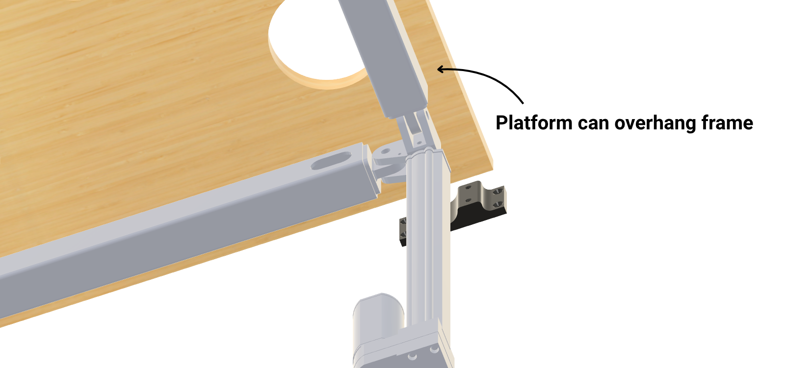
- Use ¾″ plywood for strength and rigidity.
- The platform may overhang the frame by a few inches to:
- The platform must cover all frame tubes for proper support.
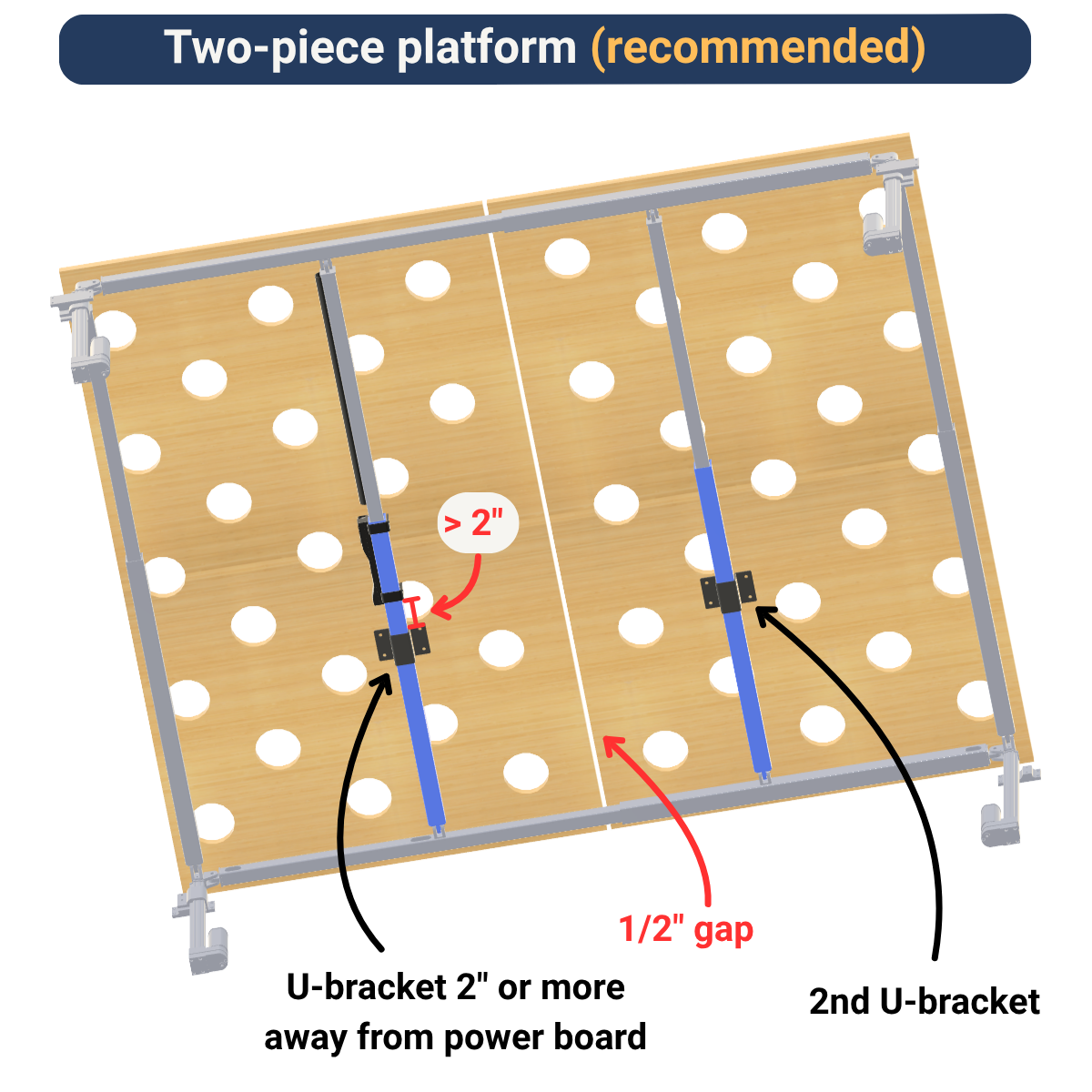
- Leave at least a ½″ gap between the two panels.
- Install two U-brackets: one on each short-beam outer tube spanning the middle of the bed.
- The U-bracket nearest the power board must be at least 2″ away from the edge of the power board, or wiring may be difficult to connect/disconnect.

When using drop mounts, you will likely need to cut a notch out of the corner of the plywood platform to avoid hitting the drop bracket and the coiled cabled.
The image below is an example.
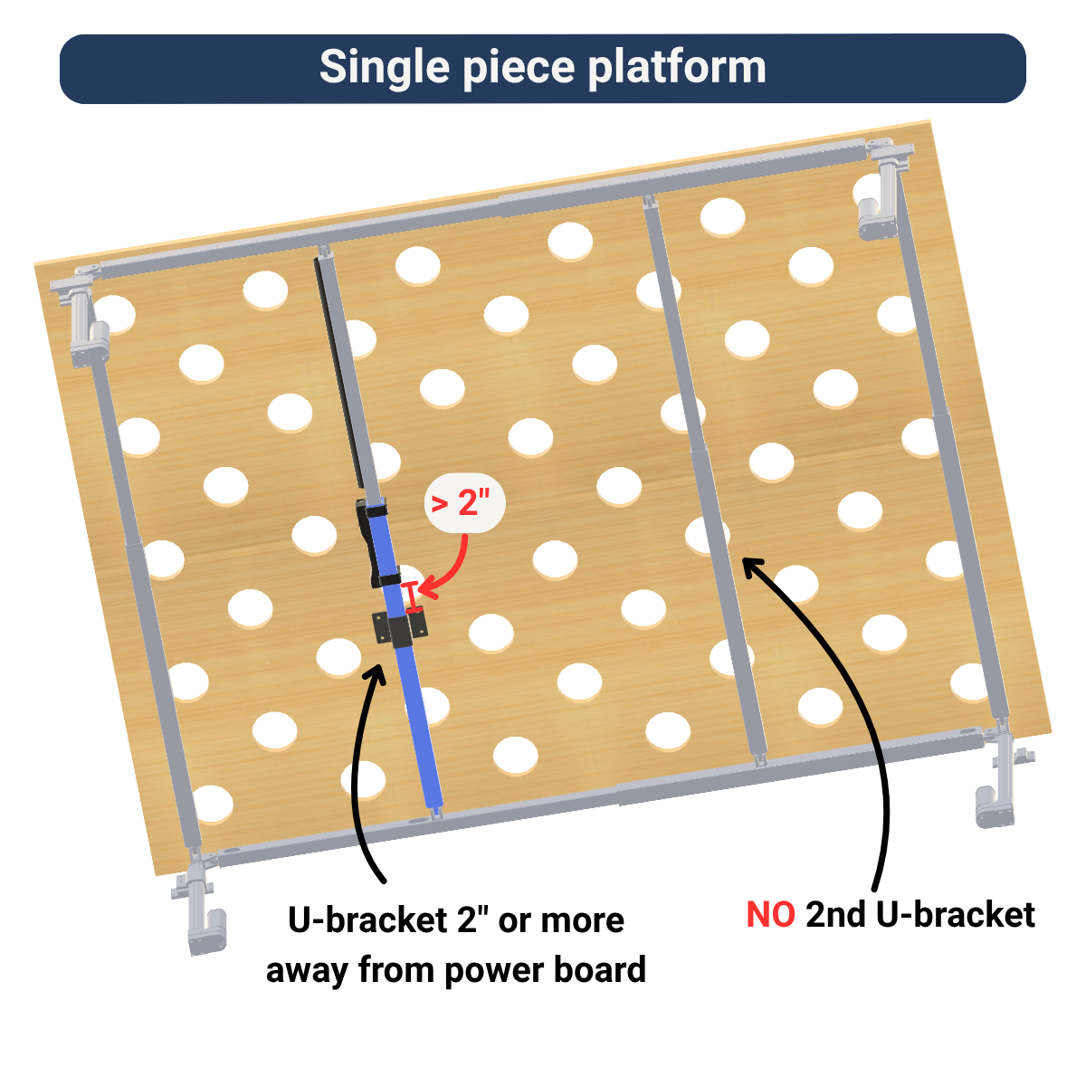
- Install only one U-bracket (on the short-beam outer tube with the power board).
⚠️ Installing two U-brackets on a single panel will cause the frame to bind when leveling.
- Keep the U-bracket at least 2″ from the power board edge for wiring clearance.
1. With the platforms and U-brackets in place, mark the hole locations.
2. Drill 5/16" holes and secure platform to U-brackets with
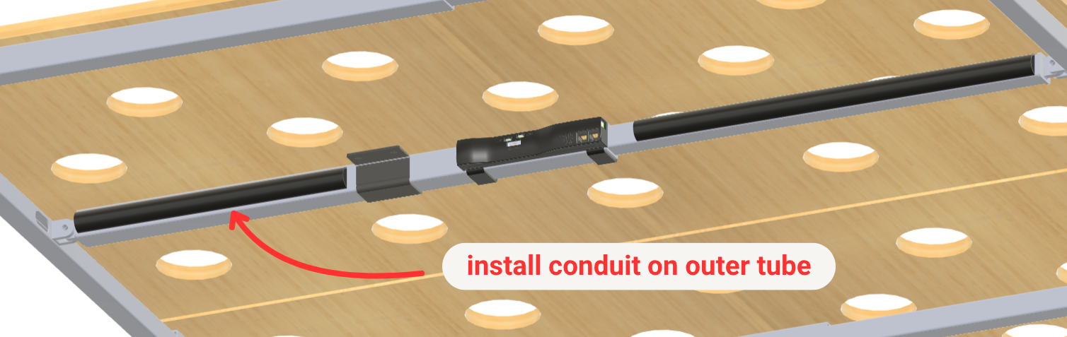
With the U-brackets in place, install the outer tube wiring conduit in a similar manner to the inner tube wiring conduit.
If the conduit won't stay closed due to cable bulk, secure with Velcro cable ties at each end.
For instructions on how to use the controller and how to adjust settings like collision detection sensitivity and auto-level set point, check out the User Manual webpage.
If you have any questions, issues, concerns, or feedback - please send us an email at support@tiltbedsystems.com!
